| Creator: Matt |
| Date: 2004-10-21 |
Rating:  |
| |
Description
A fan control can help reduce the noise made by a PC's case fans. Furthermore, you don't need the same cooling power in winter as in summer. There are a lot of fan controllers you can buy from manufacturers of cooling accessories but a true modder builds one himself!
You can build a useful fan control with the schematic shown here, and it just costs a few bucks.This schematic, used for a simple PWM controller, was used as a template. The PWM (pulse width modulation) has some advantages over a linear regulator because it needs less power. The original schematic has been modified in a few places but in general it's still more or less the same.
Part List:
€ 1x 555 IC (type doesn't matter)
€ 1x Transistor BD438 (switches max. 4A)
€ 1x Potentiometer 100k
€ 3x Diode 1N4148 (other types work as well)
€ 3x Capacitor 100nF
€ 1x Electrolytic capacitor 220µF
€ 1x Electrolytic capacitor 10µF
€ 1x Resistor 1k
€ 1x Resistor 30k
€ 1x Resistor 47k
€ 1x Resistor 150k
€ 1x Jumper 2x1
€ 1x Jumper 3x1
€ 1x Jumper 8x2
Note:
Some fans (even high quality) have problems if they are fed via a PWM. You'll notice that if the fans stop rotating and just make a low-frequency noise if you turn down the output voltage below a certain threshold. You'll have to try if your fans work. |
 | This is the schematic of the fan control based on a 555 timer IC.
A schematic created with Eagle 4.13 can be downloaded here. |
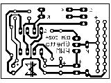 | This is the finished PCB layout (mirrored). It can be downloaded here. |
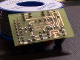 | This is the prototype PCB. It would have been more ghetto to use a rastered PCB but this wasn't necessary thanks to !mURx' etching center.
Soldering the parts shouldn't be a problem even though the PCB measures only 45mm x 25mm. |
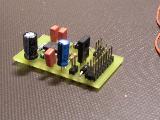 | The circuit after soldering. Only the electrolytic capacitors might cause problems if you don't have any of the correct size. If that's true just leave a bit more space between the capacitor and the PCB. |
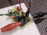 | The first test with clamps. Only one 92mm NMB fan was connected to guarantee nothing goes up in smoke. |
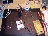 | An overview of the whole thing. The test was successful, according to the multimeter the circuit switches smoothly between 0V and 12V. Of course the measures are not accurate enough to show the PWM impulses. |
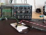 | Finally, a signal check with the oscilloscope. The signal looks a bit skewed on the picture because the clamp wasn't properly configured. After some corrections the oscilloscope showed a nice square pulse. |
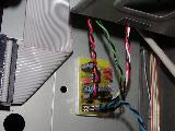 | The finished circuit after fitting it in the PC case. The transistor got a selfmade aluminum cooler although it should work without it as long as you don't connect power-hungry devices. |
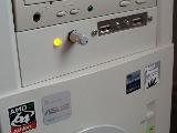 | The fan control is regulated by a potentiometer that is mounted on the front panel. The LED is directly connected to the fan outputs so its brightness varies. If the fan control malfunctions the LED will turn off. |
Rate this mod |
| The more Arnolds the better! |
|
|
| Prior ratings: 22 |

